
EasyCAD
Easy to use PCB layout software. Simple for the beginner and useful tool to designing high-frequency pattern

DesignView
Software to display and inspect your boards with a camera.

Fabricate larger boards
Fabricate part of the data, slide the board and use the camera to align and adjust for further fabrication.
After setting the line width and pad size, you can easily create a single or double-sided board. Simply double-click to switch top to bottom layer and generate pad for through hole.
Enter Dimension at Keyboard
A useful function for designing high-frequency pattern allowing you to enter dimensions using the keyboard.
Great For Anyone Familiar With Other Mechanical CAD Software
EASY CAD have the various editing commands used in other popular mechanical CAD software: extend line, parallel, corner round, corner bevel, move/copy (straight, rotation, mirror), offset, hatch and so on.
Milling Line Creation
The milling lines for the cutter are created automatically while applying a 1/2 offset for the milling cutter channel width around the outside of the completed pattern. If additional milling lines are created, unwanted copper lamination can be removed.
Status Bar Information
The X,Y coordinates of elements and the distance between the centers of two elements or the distance between their adjacent edges can be displayed.
Truetype Font Support
You can enjoy to mill a variety of Truetype Fonts.
Pursuit of usability with camera
There are many useful ways to use the camera!
With our new “Overlay Function”, no extra work is needed to check the result with magnifier (loupe); it will overlay the resulted milling path and data pattern on monitor, easy to use and very helpful function for making RF boards.
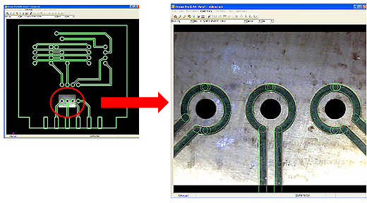
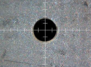
Measures the distance from fiducial point accurately.
Adjusting and aligning position is not a problem using the camera for processing double-sided boards or additional process on a completed board. Having the camera image displayed on the monitor, it gives the user an easier time and confidence that it’s in a correct position.
Pic. : Image of alignment to fabricate double-sided board
Converts Gerber, DXF
Automatically generates converted pattern data into data that can be used by the board maker CAM Program for controlling the board maker
Web Video Import Gerber
Operational Environments
OS Windows XP (SP2) / Vista / 7 / 8
*Applicable only to the XP 32 bit
CR-5000 (ZUKEN)
Protel (Altium Designer)
PADS
OrCAD
Win PCB
Eagle
Microwave Office
Auto CAD (Auto Desk)
DesignSpark PCB
And Others
EasyCAD Features
- Simple Operation for Creating Double-Sided Board
- Enter Dimension at Keyboard
- Easy to remember editing commands used popular mechanical CAD software.
- Milling Line Creation
- Status Bar Information
- Truetype Font Support
- Ability To Import Other CAD data such as Gerber – GerberX (274X) – Exellon Drill output data – DXF
Download a 30 day fully functional EasyCad
Software Upgrade Information
IMPORTANT —- End of License Reissue Service for “Flash for Windows” (November 2010)
“Flash for Windows” was upgraded to our “Design Pro” in April 2008. With this upgrade, we hereby announce to end our license reissue service for “Flash for Windows” in March 2011. 15 years has passed since the release of “Flash for Windows”. Since the OS and computer technologies have developed drastically within these years, it has brought us to the point where supporting the previous version become difficult. Upon the end of license reissue service, we maybe cause inconvenience to you. Thank you for your understanding.
At this time, please consider to upgrade your software to our latest “Design Pro”. Please contact us for the details.