Check the result with the data pattern on the monitor
|
|
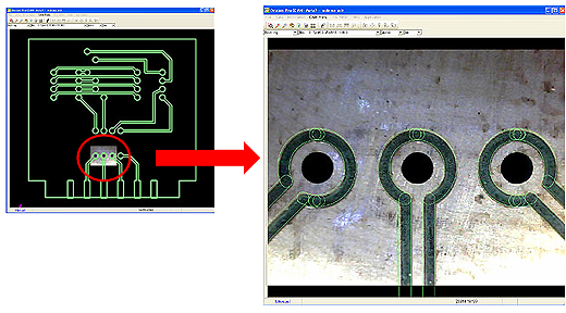
With our new “Overlay Function“, no extra work is needed to
check the result with magnifier (loupe); it will overlay the
resulted milling path and data pattern on monitor, easy to use
and very helpful function for making RF boards.
Pic. : Overlaid image of pattern and the board
|
Measures the distance from fiducial point accurately
|
|
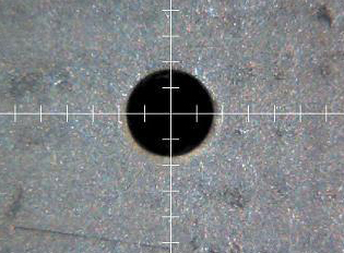
Adjusting and aligning position is not a problem using the
camera for processing double-sided boards or additional
process on a completed board. Having the camera image
displayed on the monitor, it gives the user an easier time and
confidence that it’s in a correct position.
Pic. : Image of alignment to fabricate double-sided board
 |
Fabricate boards larger than the working area
(Note: Manual Tool Change machine only)
|
|
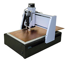
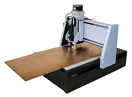
In the past, the working area was limited just its working area
for any prototyping machine. Having the camera, it opened up
opportunity to process 2,000mm boards with our “segmented
fabrication“.
 |
 |
|
Milling the front side of large PCB
|
Slide the board, milling the back side of
large PCB
|
It will fabricate part of the data, then slide the board and use
the camera to align and adjust for further fabrication. |
